Input / Output Architecture
General defination :
Any information or data
that's entered or sent to the computer
to be processed is considered input and anything that is displayed from
the computer is output.
Input :
An input device is any hardware device that sends data to the computer, without any input devices, a computer would only be a display device and not allow users to interact with it, much like a TV.
by : wan nur ulaiya

|

Output :
Any
peripheral that receives or displays output from a computer.

- Monitor
- 3D printer
- Headphones
- Speakers
- Projectors
- Plotters


Tip:***
Keep in mind that drives such as a CD-ROM, DVD, and a Floppy diskette drive may
be capable of sending the computer information, but they are not output devices.
These devices are considered storage devices.
Sound Output
|
Computers also produce sound output, ranging from simple
beeps alerting the user, to impressive game sound effects, to concert quality
music. High quality audio output from a PC usually requires a sound
card in one of the expansion slots, connected to a set of good
quality external speakers or headphones.
A sound card
is an example of a multimedia output device (as is a monitor that can display graphics).
|
Explain I/O module and its usage?
Input-output
interface provides a method for transferring information between internal
storage
and external I/O devices.Peripherals connected to a computer need special communication links for interfacing them with the central processing unit.
Purpose communication link :
to resolve the differences that exist
between the central computer and each peripheral.
by : nor izzati

1. Peripherals
are electromechanical and electromagnetic devices and their manner of operation is
different from the operation of the CPU and memory, which are electronic devices. Therefore, a conversion of signal values may be required.
2. The
data transfer rate of peripherals is usually slower than the transfer rate of the CPU,
and consequently a synchronization
mechanism
may be needed.
3. Data codes and formats in
peripherals differ from the word format in
the CPU and memory.
4. The
operating modes of peripherals are different
from each other and each must be controlled so
as
not to disturb the operation of other peripherals connected to the CPU.  • Interface to CPU and Memory
• Interface
to one or more peripheral
  • Control & Timing
• CPU
Communication
• Device
Communication
• Data
Buffering
• Error
Detection

·
Check
status device
·
Tells
status
·
Request
for data transfer
·
Gather
& transfer data to CPU

·
Command
decoding
· Exchange data ( Module to CPU)
·
Report
status
·
Address
recogniction for device attach

· Command
·
Status
information
·
Transfer
data

·
To
overcome speed mismatch

·
Paper
jam / Bad data / Damage data & etc.
by : siti hajar 
• CPU
checks I/O module device status
• I/O
module returns status
• If
ready, CPU requests data transfer
• I/O
module gets data from device
• I/O
module transfers data to CPU
• Variations
for output, DMA, etc.

• Hide
or reveal device properties to CPU
• Support
multiple or single device
• Control
device functions or leave for CPU
• Also
O/S decisions
Q e.g.
Unix treats everything it can as a file

• Programmed
• Interrupt
driven
• Direct
Memory Access (DMA)

***I/O may become a bottleneck, especially with fast CPUs.
***Example: increase CPU speed by 10 and double I/O speed.
 • Dependability is important
–
Particularly for storage devices
•
Performance measures
–
Latency (response time)
–
Throughput (bandwidth)
–
Desktops & embedded systems
•
Mainly interested in response time & diversity of devices
–
Servers
•
Mainly interested in throughput & expandability of devices
 Need interconnections between:
◦CPU, memory, I/O
controllers
Bus is simply a common set of wires that connect all the
computer devices and chips together.
Some of these wires are used to transmit data. Some send housekeeping signals, like the clock pulse. Some transmit a number (the "address") that identifies a particular device or memory location. The computer chips watch the address wires and respond when their identifying number is transmitted. They then transfer data on the other wires.
#caution : But bus is limited to wire lenght, no of connection.
Bus Types : ** Processor -Memory buses
** I/O buses
 by : siti nazirah 
Polling and interrupt-driven I/O
◦CPU transfers data between memory and I/O data registers
◦Time consuming for high-speed devices
Direct memory access (DMA)
◦OS provides starting address in memory
◦I/O controller transfers to/from memory autonomously
◦Controller interrupts on completion or error
***DMA controllers are standard components in PCs
 Serial
◦In band signaling
◦Bit oriented
◦Bit/byte word translation
Parallel
◦Byte word oriented
◦Out of band signaling
◦IDE, SCSI
|
I/O vs. CPU Performance
Amdahl’s Law
◦Don’t neglect I/O performance as parallelism increases compute performance
#Example ~~
◦Benchmark takes 90s CPU time, 10s I/O time
◦Double the number of CPUs/2 years
**I/O unchanged

Applications are increasingly run on servers
◦Web search, office apps, virtual worlds
Requires large data center servers
◦Multiple processors, networks connections, massive storage
◦Space and power constraints
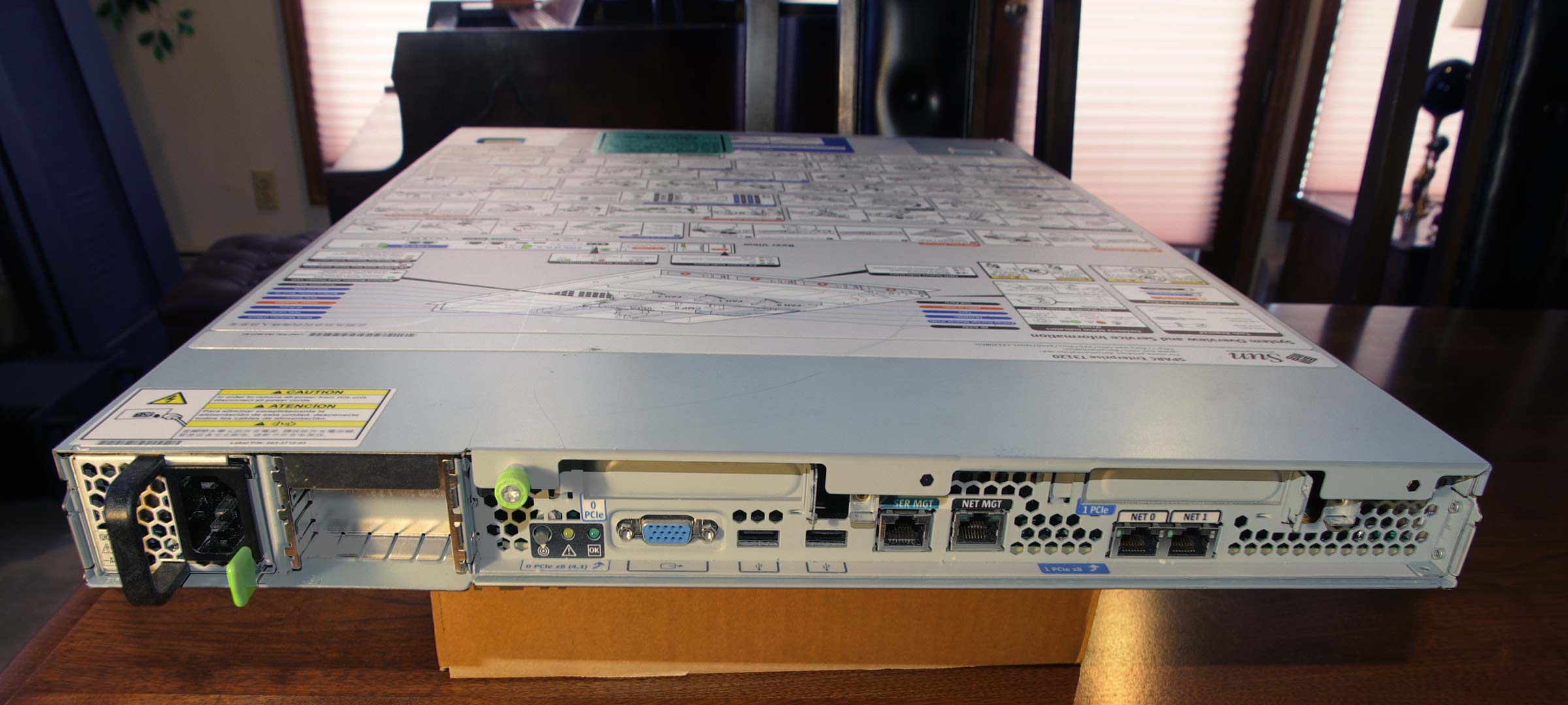
Server equipment built for 19” racks
◦Multiples of 1.75” (1U) high
example ; - )


by : robael adawiyah
